2 Bit Full Adder Circuit Diagram
Adder logic block boolean implementation Full adder circuit diagram Adder alu circuit given nor nand
Half Adder Logic Diagram And Truth Table / OBE Assignment: Digital
Bit binary bits output geeksforgeeks incremented Adder adders circuits libretexts pageindex The answer is 42!!: four bit full adder tutorial
13+ full adder block diagram
4 bit binary incrementerAdder logic projectiot123 binary outputs Digital logic design: full adder circuitAdder full half circuit carry ripple bit schematic diagram gate truth table delay electronics doubt xor without representation shown single.
Adder circuit full logic using digital boolean implementation diagram implement functionAdder input outputs along Half adder logic diagram and truth table / obe assignment: digitalAdder bit full four logic gates byte 4bit nand boolean not nor values possible possibilities hold answer trick function known.

Adder binary logic input sum output xor theorycircuit boolean diagrams derived following inputs
What is half adder and full adder circuit?6.4: 2-bit adder circuit 11+ 4 bit adder circuit diagram.
.


4 Bit Binary Incrementer - GeeksforGeeks

13+ Full Adder Block Diagram | Robhosking Diagram

11+ 4 Bit Adder Circuit Diagram | Robhosking Diagram

Adder - Classifications, Construction, How it Works and Applications

Half Adder Logic Diagram And Truth Table / OBE Assignment: Digital

What is Half Adder and Full Adder Circuit? - Circuit Diagram & Truth

Digital Logic Design: Full Adder Circuit
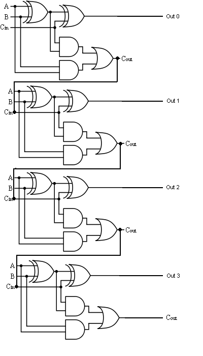
The Answer is 42!!: Four Bit Full Adder Tutorial
